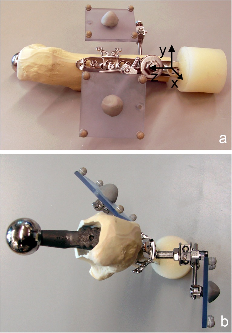
Fig. 2.
Specimen prepared for mechanical testing with two retro-reflective marker sets, consisting of four markers each, attached to the locking compression plate (LCP) (reference marker set) and to the synthetic proximal femur (a lateral view with schematic coordinate system for motion tracking; b cranial view). The reference marker set with markers aligned parallel to the LCP axis and the sagittal plane defines a Cartesian coordinate system (a) with centre on the lateral aspect of the femur on the level of the fourth LCP hole, and the z-axis pointing in the proximal direction along the central axis of the plate and the y-axis anteriorly in the plane of the plate

