Abstract
Purpose
Optimal positioning of acetabular components is crucial for maintaining stability of THA. Postoperative assessment of acetabular anteversion is a vital but difficult task. Various methods have been devised with good results for measuring anteversion on plain radiographs but these methods are either too complicated or require special objects like scientific calculators, special protectors, tables, etc. A new simplified method of measuring anteversion on plain radiographs was created based on basic geometry.
Methods
Anteversion of acetabular components was estimated on computer generated images of the acetabular cup by our method and compared with two previously established methods of Liaw and Pradhan. Measurement was done at 400 different positions of acetabular cup and compared with actual values. Another analysis was done after adding the femoral head to the acetabular component, thus obscuring some of the acetabular rim.
Results
Mean and standard deviation of error for our method was 0.77° ± 0.75° as compared to 0.93° ± 0.86° and 0.72° ± 0.68° for the methods of Liaw and Pardhan, respectively, with no significant differences from actual values. Maximal errors for our method, Liaw’s and Pradhan’s method were 3°, 4°, and 2.91°, respectively. On analysis, after the adding femoral head, there was a significant error of measurement with Liaw’s method, while our method as well as Pardhan’s remained accurate. All methods showed high inter- and intraobserver reliability.
Conclusion
Our new simplified method of measuring acetabular anteversion on plain radiographs is acceptable in comparision to other established methods and requires only routinely used goniometer and calliper.
Introduction
Amongst other factors, orientation and alignment of prosthetic components is vitally important for stability of total hip arthroplasty [1, 2], and it has been shown that malpositioning of components predisposes THA to dislocations, impingement and increased polypropylene wear rates [3–7]. Thus a lot of effort has gone into the means of determining and achieving optimal alignment, and guidelines have been drawn based on observation.
Orientation of the acetabular cup has been described in terms of inclination and anteversion or retroversion. Inclination or opening of the acetabular face is defined as the angle made by the face of acetabulum to the horizontal plane and can be directly measured from plain radiographs. Anteversion has been further classified as being planar or radiographic, true or anatomic, operative or flexion [8]. Planar anteversion is the rotation of the acetabular face along the axis defined by the intersection of the coronal plane and the plane of the acetabular face. Anatomic and operative anteversion are rotations of the acetabular component along the vertical and transverse axes, respectively.
Determination of three-dimensional alignment of the acetabular component of hip arthroplasty with precision would require nothing short of a CT scan which is impractical to obtain in every case. Methods have thus been developed to determine orientation of acetabular prostheses from two-dimensional plain radiographs [9–15]. Most of these methods have similar accuracy but differ in complexity and requirement of special tables, algorithms, specially designed protractors or calculators.
We present our new method that requires only a commonly used goniometer and divider/calliper without the need of any tables, calculators, algorithms, protractors, etc.
Rationale behind measurement of anteversion on plain radiographs
Methods of measuring acetabular anteversion from plain radiographs have evolved from complex algorithms and formulas to relatively simple calculations. However, all presently described methods employ at least some tool not routinely available with an orthopaedist at all times.
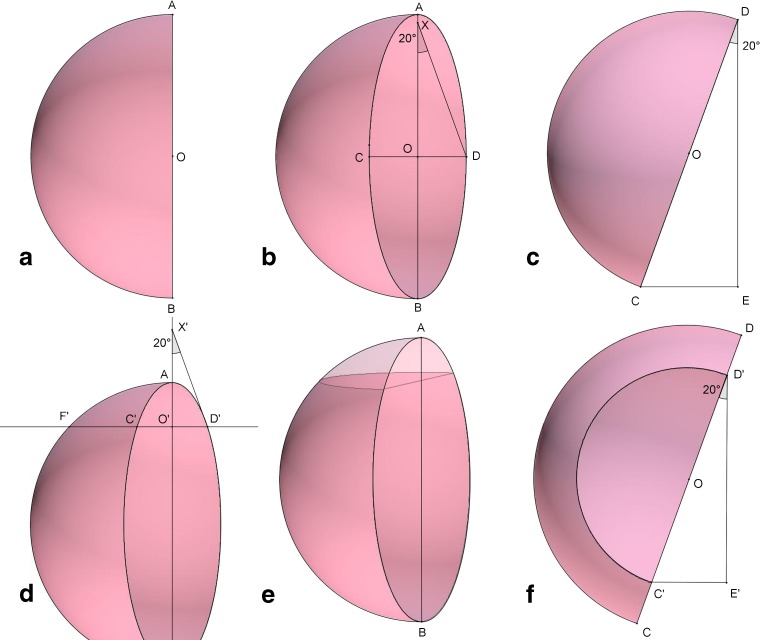
Our method employs the same concept of circular face of acetabulum being projected as an ellipse on a plane radiograph but without need of any calculations. Figure 1a represents a hemispherical cup without any anteversion and viewed from the anterior side. If anteversion is added to this cup, the open face will project an ellipse (Fig. 1b). The angle of this opening can be measured clearly if we are able to view this cup from above (Fig. 1c). In a hemispherical cup the centers of cup and ellipse will coincide (O). Segments AB and CD (Fig. 1b) represent the long and short diameters of the ellipse with AB also representing diameter of the cup. Viewing the same cup from above, points C and D will form the diameter of the cup (Fig. 1c) and the angle of anteversion is represented by angle CDE. The length CE represents the length of diameter CD viewed from the front or the short axis of the ellipse. Thus two sides of a right angled triangle—the hypotenuse and the shorter cathetus (hereafter called base)–are known and the angle can be calculated as:
 |
Fig. 1.
Rationale of measuring anteversion on plain radiographs (see text for description of individual figures)
Due to the metallic femoral head, the full extent of the ellipse is never visible on radiographs. To counteract this problem, measurements can be made at the visible part of the ellipse. A perpendicular line is dropped (Fig. 1d) from the visible circumference to the long axis intersecting the circumference at points C’ and D’ and extended to meet the outline of the cup (or circle with diameter AB in cemented cups) at point E. If the section of cup beyond this line is removed (Fig. 1e) and viewed from above (Fig. 1f), anteversion can be calculated using the same method as mentioned above with O’D’ and O’F’ as short and long diameters (Fig. 1d). Pradhan made measurements at point O’ on segment AO such that OO’ was 3/5th of length AO. At this point the segment FO’ equals 4/5th of AO and anteversion can be calculated with the sine inverse function, but this fixed point may not always be visible with large diameter heads or metal-on-metal THR.
Materials and method
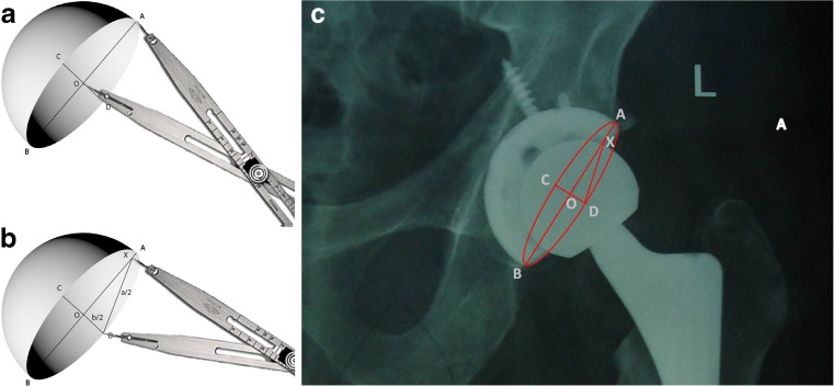
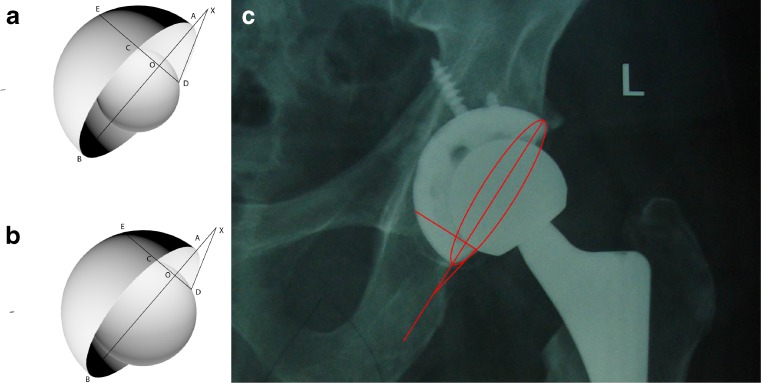
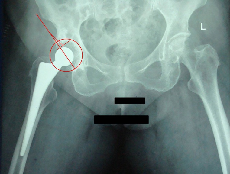
The two diameters of an ellipse, major and minor, are known to be perpendicular bisectors of each other. Thus, we draw these two diameters on plane radiograph of the acetabular component, intersecting each other at right angles at point O, with large diameter intersecting the circumference at points A and B (length = a), while the small diameter intersects the circumference at points C and D (length = b) (Fig. 2). This can be accomplished by marking the ends of a large diameter of an ellipse and then drawing a perpendicular bisector of the segment of a line between them. The angle of anteversion is then inverse sine function of b/a. For the ease of measurement and to obviate the need of trigonometric tables, a triangle with exact measurements can be drawn on the radiograph itself and the angle measured manually with a goniometer. A point X is marked on AO from the point D, such that the measurement XD equals AO (a/2). This can be very well accomplished using a divider/calliper. XOD is a right angle triangle and the angle DXO thus represents angle of anteversion (Fig. 2). In cases where the short axis of the ellipse is obscured due to metallic femoral head, a perpendicular is drawn on the part of the long axis where the acetabular margin is not obscured and points where this line intersects the margins of ellipse and circumference of acetabular cup (assuming it to be hemispherical) are marked (Fig. 3). The long axis AB is extrapolated beyond the ellipse and a point X’ is marked on it from D’ such that D’X’ equals O’E (a’/2). The angle D’X’O’ represents the angle of anteversion in this case. In cases of cemented cups, where circumference of acetabulum is not visible, a divider is used to make a point on this perpendicular which is at a distance of a/2 from the centre of the acetabular cup or a circle can be drawn with centre as point O and radius as a/2. Now short axis b’/2 and long axis a’/2 are known and angle of anteversion can be determined in a manner previously described (Fig. 4).
Fig. 2.
Method. The long (AB; length a) and short (CD; length b) axes of the ellipse are drawn which intersect each other at a right angle at point O. Radius of acetabular component is measured as half of length AB (a/2; length OA) (a). The angle of anteversion is drawn after marking a point on the long axis such that its distance from the point of intersection of the short axis and acetabular ring (point D) equals the radius of acetabular component (b). The angle DXO is the angle of anteversion. Measurement of actabular anteversion in uncemented total hip replacement (c)
Fig. 3.
Measurement of anteversion with femoral head of size 50 % (a) and 66 % (b) of that of the acetabular cup. A perpendicular is dropped from the visible part of the ellipse to its diameter to intersect the diameter and the outline of the acetabular cup at points O and E, respectively. Distance OE (a’) is measured and a point X is marked on the long diameter at a distance of OE from point D. The angle DXO is the angle of anteversion. Measurement of anteversion in uncemented total hip replacement using only the visible part of acetabular ring (c)
Fig. 4.
Measurement of anteversion in a cemented acetabular component after drawing a circle with diameter and center same as the ellipse
We used a computer generated model of acetabulum oriented at a precisely known angle and applied our method and compared it with other previously established methods of measuring anteversion described by Pradhan [11] and Liaw et al [15]. The CS5 extended version of Adobe Photoshop software was used to create simulated models of acetabulum at varying degrees of anteversion and inclination. We used our method on an initial 100 simulated radiographs with anteversion ranging from 5° to 60° and error of measurement was calculated for each value. This analysis showed that measurements were accurate only in the range of 5° to 40°. Anteversion was then measured in 400 different simulated positions of acetabular cup at various angles of anteversion (within 5–40°) and inclination. These measurements were repeated after adding a model of femoral head to the acetabular model, measuring 50 % and 66 % of the size of acetabular cup. Each measurement was performed by three independent observers to ascertain interobserver reliability. Intraobserver reliability was further tested by comparing measurements made by one observer at an interval of three weeks.
Statistical analysis
This was performed using the IBM SPSS v.19 software (SPSS Inc., Chicago, Illinois). We used unpaired t-test for comparison of error in measurement of anteversion up to 40° with anteversion more than 40°. Inter- and intraobserver reliability was measured by calculating intraclass correlation coefficient (ICC) for each method. All measurements with three different methods were compared with actual value using paired t-test. A p-value < 0.05 was considered statistically significant.
Results
During the initial 100 measurements it was determined that most accurate measurements were made up to 40° of anteversion and increase in angle beyond this value created larger errors in measurement (p < 0.01). There was, however, no relation of error in measurement with increase or decrease in angle of inclination. All errors of >3° or more occurred in anteversion angles of >40°.
All methods showed high inter- and intraobserver reliability (Table 1). The mean and standard deviation of error for our method was 0.77 ± 0.75 as compared to 0.93 ± 0.86 and 0.72 ± 0.68 for the methods of Liaw and Pradhan, respectively (Table 2). The median of this error was within 1° for all three methods with maximal errors of 3, 4, and 2.91 for ours, Liaw’s and Pradhan’s methods, respectively. There was no statistically significant difference between the three methods.
Table 1.
Intra- and interobserver reliability of measurements
| Method | Interobserver | Intraobserver | ||
|---|---|---|---|---|
| ICC | 95 % Cl | ICC | 95 % Cl | |
| Pradhan | 0.936 | 0.893–0.974 | 0.953 | 0.925–0.984 |
| Liaw | 0.893 | 0.856–0.937 | 0.924 | 0.907–0.943 |
| Our method | 0.927 | 0.879–0.965 | 0.941 | 0.918–0.975 |
ICC intraclass correlation coffecient, CI confidence interval
Table 2.
Comparisons of various methods used for measuring anteversion of acetabular component (with or without femoral head) with actual values
| Method | Without head | With 50 % head | With 66 % head | |||
|---|---|---|---|---|---|---|
| Mean (SD) | p-valuea | Mean (SD) | p-valuea | Mean (SD) | p-valuea | |
| Pradhan | 0.72 (0.68) | 0.921 | 0.83 (0.71) | 0.934 | 1.12 (0.87) | 0.219 |
| Liaw et al. | 0.93 (0.86) | 0.873 | 2.36 (1.39) | 0.03 | 3.85 (2.68) | <0.001 |
| Present study | 0.77 (0.75) | 0.895 | 0.89 (0.80) | 0.917 | 0.94 (0.83) | 0.821 |
SD standard deviation
a Paired t-test
In simulated radiographs where the central part of the ellipse was obscured by the femoral head of 50 % size of the acetabular cup, the mean and standard deviation of error was 0.89 ± 0.80 for our method as compared to 2.36 ± 1.39 and 0.83 ± 0.71 for the methods of Liaw and Pradhan, respectively. In similar measurements with femoral head of 66 % size, measurements were 0.94 ± 0.83 and 1.12 ± 0.87 for our method and that of Pradhan, respectively, as compared to 3.85 ± 2.68. There was a statistically significant difference between the accuracy of Liaw’s method as compared to the other two methods for both sizes of femoral heads, but greater for larger diameter heads (Table 2).
Discussion
CT scan is perhaps the best, albeit impractical, method for ascertaining acetabular anteversion due to involved cost and radiation exposure whereas plain radiographs are an easily accessible, cheap and safe source for determining anteversion after THA. But using two-dimensional radiographs to determine three-dimensional angles is fraught with obvious limitations.
It has been determined that at a conventional distance of 115 cm for obtaining radiographs, there is an error of 5.46° in the measurement of anteversion angle in the transverse plane, due to divergence of X-rays, when radiograph is centred at the pubic symphysis [13]. The change in angle in one direction can affect angles in all planes depending on the site of centre of radiograph [16]. These errors can be corrected by applying simple trigonometric functions based on three dimensional geometry. The accuracy of all currently used methods for determination of acetabular anteversion from plain radiographs is thus dependent on obtaining high quality radiographs centred perfectly or nearly so on the acetabular cup.
The methods previously described for measurement of anteversion on plain radiographs can be classified as trigonometric, protractor, flouroscopic or CT scan methods. The trigonometric methods as described by Lewinnek et al. [1] and Pradhan [11] can give very accurate measurements but need routine use of a scientific calculator with trigonometric functions to calculate arc sine function. Lewinnek’s method employs use of length of both diameters of ellipse while Pradhan measured anteversion at a point 3/5th the length of the large radius away from the centre of ellipse. Various authors have designed their own protectors for direct reading of anteversion from plain radiographs with variable accuracy. The goniometer of Fabeck et al. [12] is fairly accurate but drawing the obscured part of the ellipse is required and sometimes the circles inside the goniometer do not match the side of the acetabular cup which can be a source of error and increase the complexity of this method. The protector of Liaw et al. [14] is simpler in form, convenient and more accurate but still requires guessing of obscured parts of the ellipse. The protector designed by Widmer [13] has been shown to be imprecise and we have found it to be inaccurate in comparison to other methods. Liaw et al. [15] designed a protector on the principle similar to Widmer but removed the inaccuracies and showed highly accurate results; we have made similar observations. Despite its accuracy we found the necessity of guessing obscured parts of the acetabular rim a constant cause for concern when a femoral head was added to the picture. Measuring anteversion after addition of the femoral head affected all three methods in our study, but more so the Liaw’s method, and this difference was magnified with larger size of femoral head which obscured a larger part of the acetabular rim. On these simulated radiographs, our method and that of Pradhan was significantly better than Liaw’s method. This possible discrepancy in results can be explained by the fact that in their article, Liaw et al. [15] seemed to have used simulated radiographs for the acetabular component only without addition of a femoral head. Moreover, both Widmer and Liaw protectors are difficult to use in cemented acetabular replacements as they require an accurate outline of acetabular cups which is not visible in polyethylene cups and can only be guessed or has to be drawn with a compass, which further complicates the procedure. Pradhan’s method used the part of ellipse which is at a distance of 3/5th the radius of the ellipse from its centre. With routine use of large diameter femoral heads these days, the use of Pradhan’s method is limited by the fact that acetabular margin will be obscured at the desired place in most cases of large diameter head. For the acetabular margin to be visible at a distance of 3/5th the length of its radius from the centre, the diameter of the acetabular cup has to be 5/3 times that of femoral head, implying that for a 36 mm head acetabular size of up to 60 mm is desired for use of Pradhan’s method, making it redundant in many cases. Although CT scan methods should provide accurate measurements, Olivecrona et al. [17] have reported an interobserver error of 2.3°, which is higher than or similar to some of the methods described for radiographic methods. This can possibly be due to artefacts produced by metallic implant or operational complexities. In another CT-scan-based study, Kalties et al. [18] showed superiority of CT scan over the protector of Widmer in measuring anteversion; however, this protector has been shown to be relatively inaccurate. The principal advantage of CT scan is its freedom from inaccuracies from patient positioning, which is the frequent cause of error for plain radiographs. Another excellent method of measuring anteversion on radiographs is the use of software designed for measuring position of THA components like EBRA. Although it is freely available and has been proven to be accurate in several studies, its use is still not widespread.
We believe that although some of the methods for measuring anteversion on plain radiographs are accurate in controlled conditions, these might not show similar accuracy in clinical practice since perfectly centred radiographs are rarely obtained, but these methods may still provide fairly accurate estimates.
Conclusion
Our method, although similar in principle to previously described methods, simplifies the process and does not require any special protector, calculator, or table, but instead uses a routinely available goniometer and a divider/calliper. This method can be applied equally well for uncemented and cemented THA and requires only one place where the acetabular rim is clearly visible.
Acknowledgments
Conflict of interest
The authors declare that they have no conflict of interest.
References
- 1.Lewinnek GE, Lewis JL, Tarr R, Compere CL, Zimmerman JR. Dislocations after total hip-replacement arthroplasties. J Bone Joint Surg Am. 1978;60(2):217–220. [PubMed] [Google Scholar]
- 2.McCollum DE, Gray WJ. Dislocation after total hip arthroplasty: causes and prevention. Clin Orthop Rel Res. 1990;261:159–170. [PubMed] [Google Scholar]
- 3.Robinson RP, Simonian PT, Gradisar IM, Ching RP. Joint motion and surface contact area related to component position in total hip arthroplasty. J Bone Joint Surg Br. 1997;79(1):140–146. doi: 10.1302/0301-620X.79B1.6842. [DOI] [PubMed] [Google Scholar]
- 4.Kummer FJ, Shah S, Iyer S, DiCesare PE. The effect of acetabular cup orientations on limiting hip rotation. J Arthroplasty. 1999;14(4):509–513. doi: 10.1016/S0883-5403(99)90110-9. [DOI] [PubMed] [Google Scholar]
- 5.D’Lima DD, Urquhart AG, Buehler KO, Walker RH, Colwell CW., Jr The effect of the orientation of the acetabular and femoral components on the range of motion of the hip at different head-neck ratios. J Bone Joint Surg Am. 2000;82(3):315–321. doi: 10.2106/00004623-200003000-00003. [DOI] [PubMed] [Google Scholar]
- 6.Jolles BM, Zangger P, Leyvraz PF. Factors predisposing to dislocation after primary total hip prosthesis: a multivariate analysis. J Arthroplasty. 2002;17(3):282–288. doi: 10.1054/arth.2002.30286. [DOI] [PubMed] [Google Scholar]
- 7.Schutte H, Lipman AJ, Bannar SM, et al. Effects of acetabular abduction on cup wear rates in total hip arthroplasty. J Arthroplasty. 1998;13(6):621–626. doi: 10.1016/S0883-5403(98)80003-X. [DOI] [PubMed] [Google Scholar]
- 8.Murray DW. The definition and measurement of acetabular orientation. J Bone Joint Surg Br. 1993;75(2):228–232. doi: 10.1302/0301-620X.75B2.8444942. [DOI] [PubMed] [Google Scholar]
- 9.Visser JD, Konings JG. A new method for measuring angles after total hip arthroplasty. A study of the acetabular cup and femoral component. J Bone Joint Surg Br. 1981;63(4):556–559. doi: 10.1302/0301-620X.63B4.7298684. [DOI] [PubMed] [Google Scholar]
- 10.Ackland MK, Bourne WB, Uhthoff HK. Anteversion of the acetabular cup. Measurement of angle after total hip replacement. J Bone Joint Surg Br. 1986;68(3):409–413. doi: 10.1302/0301-620X.68B3.3733807. [DOI] [PubMed] [Google Scholar]
- 11.Pradhan R. Planar anteversion of the acetabular cup as determined from plain anteroposterior radiographs. J Bone Joint Surg Br. 1999;81(3):431–435. doi: 10.1302/0301-620X.81B3.9067. [DOI] [PubMed] [Google Scholar]
- 12.Fabeck L, Farrokh D, Tolley M, Descamps PY, Gebhart M, Delincé P. A method to measure acetabular cup anteversion after total hip replacement. Acta Orthop Belg. 1999;65(4):485–491. [PubMed] [Google Scholar]
- 13.Widmer KH. A simplified method to determine acetabular cup anteversion from plain radiographs. J Arthroplasty. 2004;19(3):387–390. doi: 10.1016/j.arth.2003.10.016. [DOI] [PubMed] [Google Scholar]
- 14.Liaw CK, Hou SM, Yang RS, Wu TY, Fuh CS. A new tool for measuring cup orientation in total hip arthroplasties from plain radiographs. Clin Orthop Relat Res. 2006;451:134–139. doi: 10.1097/01.blo.0000223988.41776.fa. [DOI] [PubMed] [Google Scholar]
- 15.Liaw CK, Yang RS, Hou SM, Wu TY, Fuh CS. Measurement of the acetabular cup anteversion on simulated radiographs. J Arthroplasty. 2009;24(3):468–474. doi: 10.1016/j.arth.2007.10.029. [DOI] [PubMed] [Google Scholar]
- 16.Goergen TG, Resnick D. Evaluation of acetabular anteversion following total hip arthroplasty: necessity of proper centring. Br J Radiol. 1975;48(568):259–260. doi: 10.1259/0007-1285-48-568-259. [DOI] [PubMed] [Google Scholar]
- 17.Olivecrona H, Weidenhielm L, Olivecrona L, Beckman MO, Stark A, Noz ME, Maguire GQ, Jr, Zeleznik MP, Svensson L, Jonson T. A new CT method for measuring cup orientation after total hip arthroplasty: a study of 10 patients. Acta Orthop Scand. 2004;75(3):252–260. doi: 10.1080/00016470410001169. [DOI] [PubMed] [Google Scholar]
- 18.Kalteis T, Handel M, Herold T, Perlick L, Paetzel C, Grifka J. Position of the acetabular cup—accuracy of radiographic calculation compared to CT-based measurement. Eur J Radiol. 2006;58(2):294–300. doi: 10.1016/j.ejrad.2005.10.003. [DOI] [PubMed] [Google Scholar]


