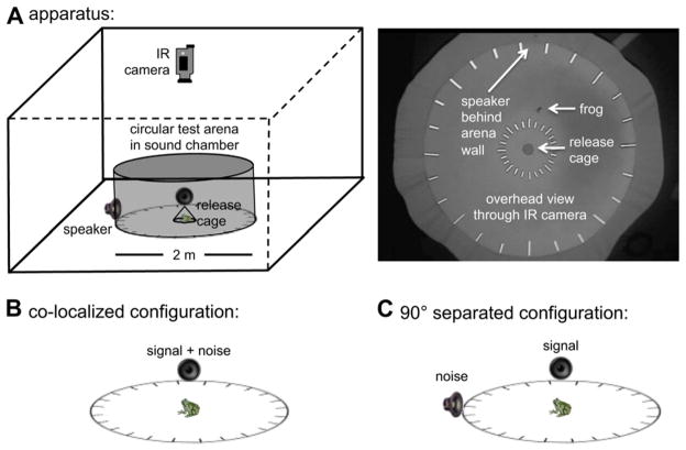
Fig. 3.
Test apparatus and signal-masker configurations. A) The schematic diagram on the left illustrates the 2-m diameter circular test arena in a sound chamber and shows the positions of speakers, the central release point, and the infrared (IR) sensitive camera. On the right is shown an actual screen-shot from an IR video recording of a gray treefrog responding in a phonotaxis test. The floor or the arena was dark gray and the walls black, though the latter reflect as gray under IR illumination. B) In the co-localized configuration, signals and maskers were broadcast from the same speaker. C) In the separated conditions, signals and maskers were broadcast from two speakers positioned 90° apart around the perimeter of the circular arena. Note: frogs, speakers, and arenas are not drawn to scale in the schematic representations.

