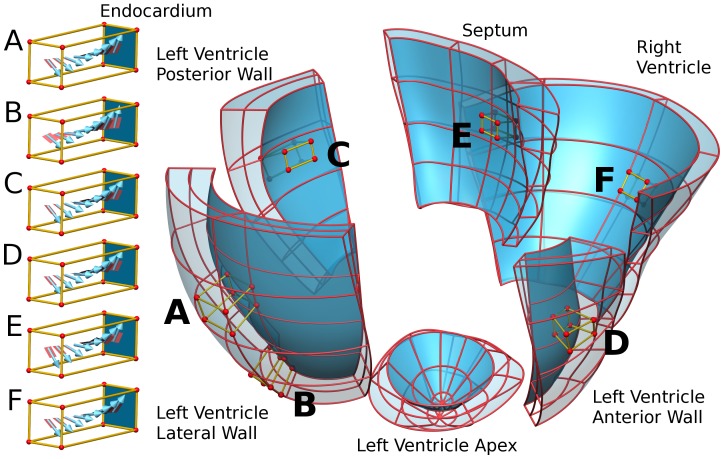
Figure 1. Patient specific model mesh geometry.
Cubes show the regional variation in the fibre orientation in the A) mid LV lateral free wall, B) apex LV lateral free wall, C) LV posterior wall, D) LV anterior wall, E) septum and F) RV free wall. The mesh is dissected into labeled regions of the heart.

