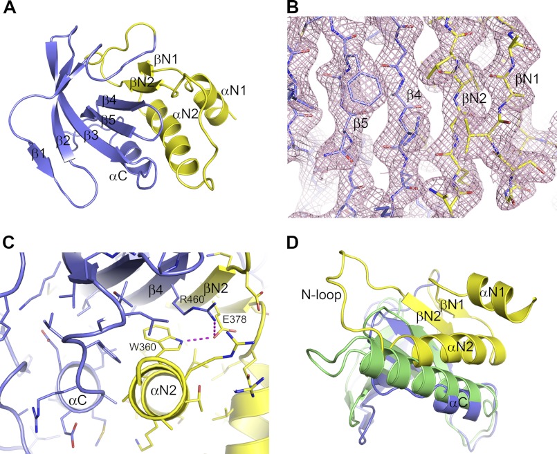
FIGURE 3.
N-terminal extension to the NIK kinase domain. A, extended N-terminal lobe of the NIK kinase domain. The typical N-terminal lobe of the kinase domain is shown in slate, and the N-terminal extension is shown in yellow. B, packing of strand βN2 of the N-terminal extension with strand β4 in the kinase N-terminal lobe. The pink mesh represents the 2Fo − Fc electron density map. C, packing interactions between the N-terminal extension and the kinase N-terminal lobe. D, position of helix αC in NIK in comparison with that in PhK, shown in green.

