
FIGURE 6.
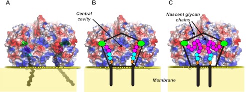
A, model showing the location of UDP-Galf (green) and β-d-Galf-(1→5)-β-d-Galf-(1→4)-α-l-Rhap-(1→3)-α-d-GlcpNAc-decaprenyl-pyrophosphate located inside the central cavity of the GlfT2 tetramer during glycan synthesis. Different parts of the lipid-linked acceptor are colored as follows: Galf residues magenta; Rhap cyan; GlcpNAc cyan; pyrophosphate orange, and decaprenol black. The approximate location of the junction between the hydrophilic and hydrophobic portions of the membrane is denoted by yellow spheres, as calculated by the PPM server (54). Semi-transparent electrostatic surface potential representation of GlfT2 (red, negatively charged; white, neutral; blue, positively charged). B, pentagon overlaid onto GlfT2 shows the approximate extent of the hollow core inside the tetramer. The locations of different parts of the lipid-linked acceptor and UDP-Galf are shown schematically and colored as in A. C, schematic diagram illustrates how two nascent chains (each eight Galf residues long in this example) are expected to form a loop extending into the central cavity formed by the tetramer and the lipid bilayer.