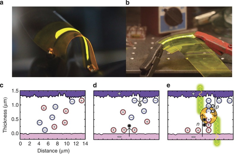
Figure 2. Key aspects of LEC operation.
(a) Photograph of a slot-die–coated LEC, illustrating the bidirectional light emission and the device conformability. (b) Light emission from a semitransparent slot-die–coated LEC following >6 months storage in a glove box. The devices depicted in a and b were driven at V=7 V. (c) Schematic structure of a pristine LEC device, indicating the existence of mobile (red) cations and (blue) anions in the active layer and the rough (blue) anodic and (purple) cathodic interfaces. (d) The electric double-layer formation and the initial electron (solid circles) and hole (open circles) injection within the same device following the application of a voltage bias. (e) The light emission (yellow-green) from the in-situ formed p–n junction at steady state.

