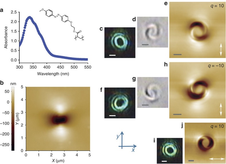
Figure 2. Light-induced surface relief patterns on the azo-polymer film.
(a) Absorption spectrum of the azo-polymer used in this work. Inset: polymer structure. (b) Surface relief pattern induced by a focused Gaussian beam (topological charge q=0). The material displacement leads to a two-lobed pattern oriented along the beam polarization direction (y-axis), as already reported in previous works7,8. (c) Optical micrograph of the intensity pattern of a LG-like vortex beam having topological charge q=10, focused by a 1.3 NA oil-immersion microscope objective on the surface of a coverslip where a metallic mirror is inserted in the place of the sample. (d) Optical micrograph of the polymer surface relief pattern generated by the focused q=10 vortex beam (linearly polarized along the y-direction). The image is taken by means of the same objective used to illuminate the sample. (e) AFM image of the same surface relief pattern as in panel d. (f) Optical micrograph of the intensity pattern when the vortex handedness is inverted (topological charge q=−10; still linearly polarized along the y-direction). (g) Optical micrograph of the polymer surface relief pattern induced after inverting the vortex handedness. (h) AFM image of the same structure as in panel g. (i) Optical micrograph of the intensity pattern obtained for a vortex beam with q=10, when the light polarization direction is rotated by 90° (so as to be parallel to the x-axis). (j) AFM surface relief pattern corresponding to the illumination conditions of panel i: the two arms of the spiral are rotated by 90°, as compared with the pattern shown in panel e. The white arrow in panels e, h and j indicates the polarization direction of the light. The scale bars in panels c–j correspond to 1 μm.

