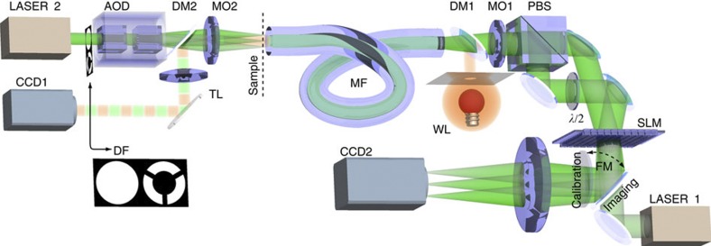
Figure 1. Experimental geometry for the bright- and dark-field microscopy based on multimode fibre image transfer.
During the calibration, light propagates from LASER 1 (operating at 1,064 nm) through the multimode optical fibre (MF, NA=0.22, 50 μm core diameter) onto the detector CCD1, imaging the fibre input facet (the sample plane). To couple into both polarization states, we split the light signal at the SLM into two pathways (superimposing different phase gratings20) that are later recombined on a polarizing beam splitter (PBS) before the resultant beam is coupled into the fibre by a microscope objective (MO1). LASER1 and CCD1 are only used for the calibration and subsequent verification of the imaging performance, and are not directly involved in the imaging process. A second laser (LASER 2) is used as an illumination signal during the imaging procedure. It is focused onto the sample plane by a second microscope objective (M02) and positioned in the plane by an AOD. In this manner, we can couple the light into the fibre from the opposite side in a controllable manner: we can generate focal spots (backwards propagating sample modes) or by rapid steering of the beam achieve arbitrary intensity patterns that simulate sample images. This way we can also generate a uniform spatially incoherent but monochromatic sample illumination, that we can then use for imaging of sample objects. Light from the sample plane propagates through the fibre onto the SLM chip where it is modified for imaging and consequently focused on CCD2 by a camera objective (CO). As the illuminating laser beam (LASER2) provides a larger NA than the multimode fibre, we can easily modify the system for dark-field imaging. Using an annular filter (DF) in a Fourier plane MO2, we restrict transmission to only those spatial frequencies exceeding the NA of the fibre. Such high-frequency components that directly propagate through an empty sample cannot be coupled into the fibre and thus do not contribute to the signal at CCD2. Only light redirected into the fibre by scattering from the object is coupled into the fibre thereby making the object visible.

