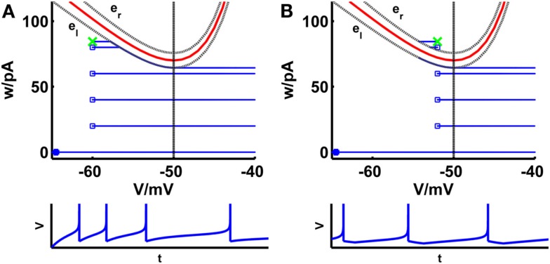
Figure 1.
Comparison of phase planes of the simpAdEx for sharp (A) and broad (B) reset. If the steady-state reset point [(Vr, wr); green cross] is below the V-nullcline (red curve) the spiking pattern corresponds to a sharp reset (no undershoot), otherwise it is broad (associated with an after-hyperpolarizing current or undershoot). The trajectory is given in blue with the blue filled square representing the initial point and the open blue squares indicating the reset points. The lower panels show the voltage traces corresponding to these trajectories. The dashed vertical line marks the threshold VT beyond which the trajectory runs strictly parallel to the abscissa. The two gray dashed lines present the functions el and er described in the text. Note that the distances of the envelopes to the V-nullcline have been enlarged for clarity.

