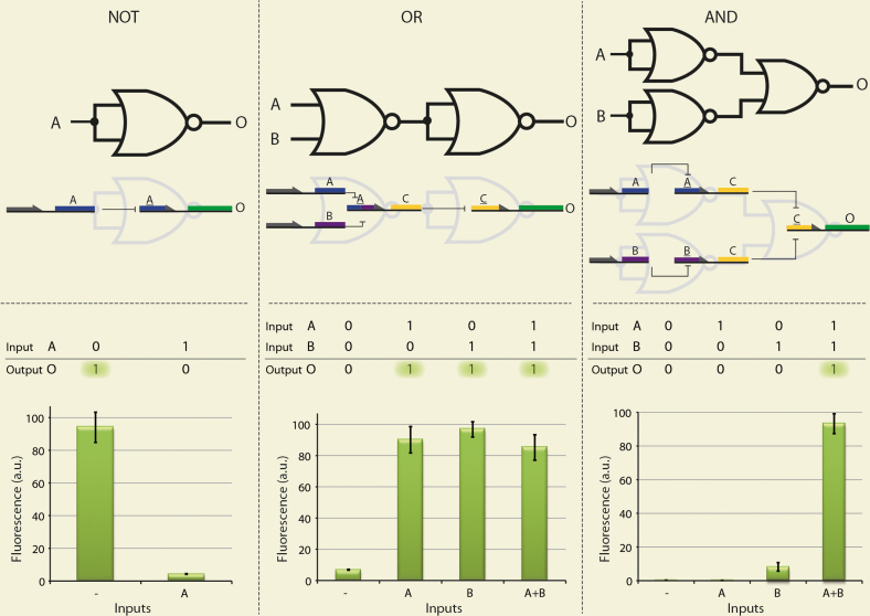
Figure 2. Molecular implementation of basic logic gates assembled by the NOR gate.
A, B and C and A, B and C represent the TFs LacI, TetR and λ-Repressor and their corresponding potential binding regions Lac-Operator, Tet-Operator and λ-Operator, respectively. O represents GFP. (a) NOT gate. If and only if (IFF) A is present, its corresponding promoter which controls the expression of the output protein is blocked, resulting in a ‘0’ output signal. (b) OR gate. IFF both A and B are absent, the expression of C is enabled, which in turn represses its promoter that controls the expression of the output protein, resulting in a ‘0’ output signal. (c) AND gate. Both A and B are needed to repress C, which in turn controls the expression of the output protein. Thus, IFF both input signals are ‘1’ the output signal is ‘1’. Arbitrary unit (a.u.) is calculated as fluorescence\O.D2. Fluorescence values and their error bars are calculated as mean ± s.d. from three experiments.

