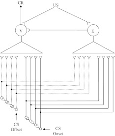
Fig. 3.
Diagram of the tapped delay-line network (from Desmond and Moore 1991). CS onset and CS offset are assumed to activate separate tapped delay-line stimulus traces. The taps form modifiable connections—denoted by closed  synaptic terminals—with the V and E units. CR is generated when V-unit connections that have positive weights are activated

