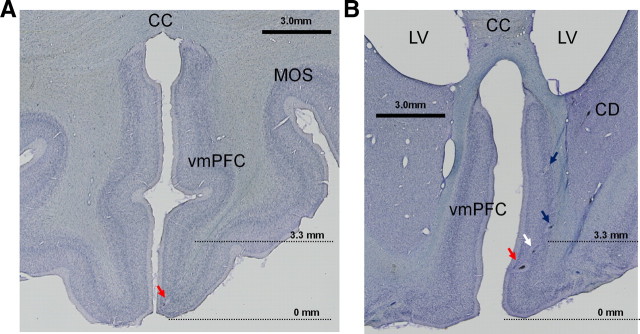
Figure 14.
Histological confirmation of recording sites within the vmPFC. A, A coronal section 14 mm anterior to the anterior commissure (AC) showing an electrolytic mark at which a positive neuron was recorded. B, A coronal section of the vmPFC 10 mm anterior to the AC. Three electrolytic marks (shown by 3 arrows) along a recording track indicate the recording sites of a positive neuron (red arrow), nonsignificant neuron (white arrow), and negative neuron (blue arrow). A fourth mark (blue arrow dorsal to the 3 marks) indicates the recording site of a negative neuron. The positive neurons in A and B were judged to be in the ventral vmPFC (because they were below the 3.3 mm transition point), whereas the negative neurons were judged to be in the dorsal vmPFC. Locations of the two histological slices are shown on a drawing from a parasagittal MR image through the vmPFC in Figure 3A and correspond to coronal MR images shown in Figure 3, B and C. The transition point between the ventral-positive region and the dorsal-negative region (3.3 mm from the bottom; see Fig. 3) is indicated by dotted lines. CD, Caudate nucleus; CC, corpus callosum; LV, lateral ventricle; MOS, medial orbital sulcus.

