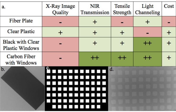
Fig. 1.
(a) Attributes of possible detector case designs for the detector panel. (b) Single x-ray frame from a DBT scan showing attenuation from a thin fiber plate. (c) Depiction of a detector case model with windows over the locations of the detectors. (d) X-ray frame from DBT scan indicating attenuation of a panel with windows.

