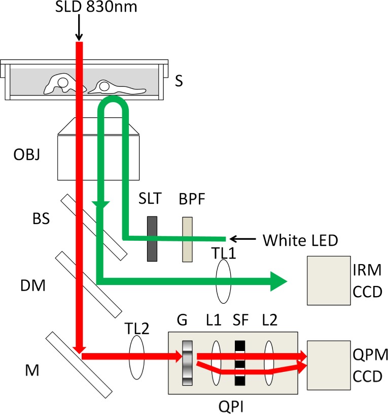
Fig. 1.
Schematic diagram of QPM-IRM imaging setup. Illumination light of SLD 830nm (red line) for QPM imaging was transmitted through a specimen (S). Transmitted light image was formed by an objective lens (OBJ) and a tube lens (TL2). The image was led to the quantitative phase imaging (QPI) unit. Optical setup of the QPI unit was described in Fig. 2(a) in detail. The QPI unit consisted of a grating apparatus (G), a spatial filter (SF) to be used as a sample and reference image and a couple of relay lenses (L1 and L2). Interference image was formed onto CCD camera (QPM CCD). White LED illumination light (green line) for IRM imaging was selected with a wide-bandwidth band-pass filter (BPF) and irradiated to the bottom side of specimen through an aperture slit (SLT). Reflection interference image form the specimen was formed onto another CCD camera (IRM CCD) by a tube lens (TL1) after being reflected by a long-pass dichroic mirror (DM) through a beam splitter (BS).

