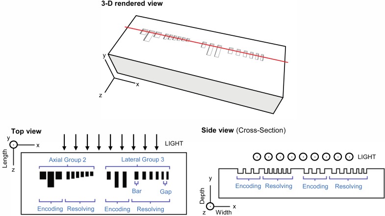
Fig. 1.
3-D rendered (above) and schematic (below) layouts of the optical phantom. Submerged structures (bars) are shown in black in the schematic top view. The location of the side-view cross section is shown by the red line in the 3-D rendered view. Axes map to definitions of depth, width and length referred to throughout this paper. Within each group, only one dimension (either width or length) varies between the six resolving bars; these are listed in Table 1. Dimensions are not to scale.

