
Figure 2. Initial model of Tsr dimer.
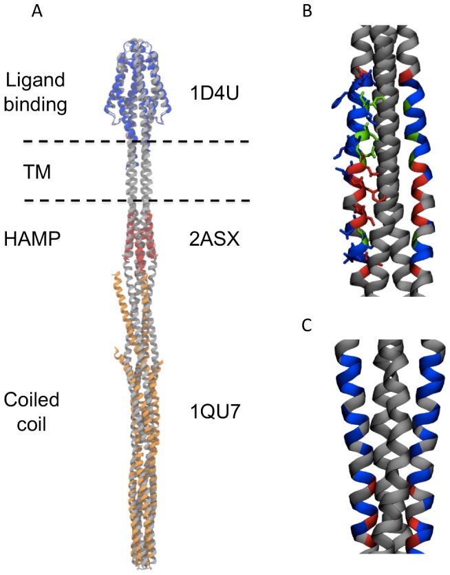
A Initial symmetric dimer in grey, overlaid onto the aligned crystal structures (ligand binding domain in blue, HAMP domain in red, and coiled coil region in orange). AS2 helices are positioned on the left and right of the HAMP domain. (B) and (C) Disulphide mapping data, plotted as colours on the surface of the TM domain for B TM1 and C TM2. Red residues crosslink strongly, green residues crosslink to an intermediate extent, and blue residues do not crosslink. In both diagrams it can be seen that higher crosslinking efficiency residues face their dimeric partner, largely in agreement with experimental data (TM2 appears to match experimental data better than TM1).