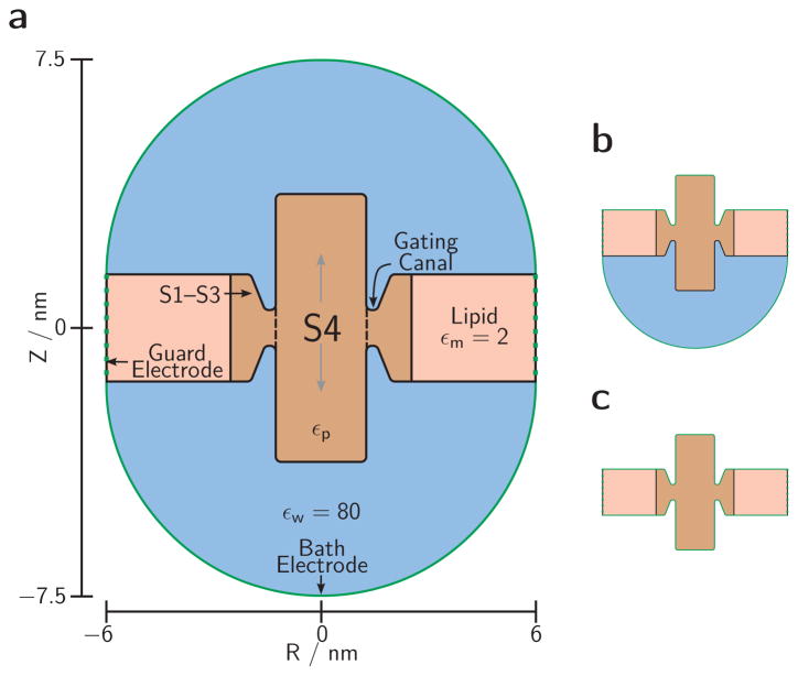
Fig. 1. Simulation cell.
(a) The 3D setup is produced by rotating this cross-section about its vertical axis. Green lines are electrode surfaces bounding the cell. Black lines are dielectric boundaries separating uniform dielectric regions: baths (blue), membrane lipids (pink), and protein (brown) with dielectric coefficient εp (varied between 2 and 16). Charges on the protein side chains (see Fig. 2) are embedded in the protein dielectric region in varied geometries. We simulate a single VS sensor domain (S1–S4) modeled as a central S4 cylinder surrounded by a ring of protein material including the S1–S3 transmembrane domains. The junction between these protein domains is narrowed to less than the membrane thickness by circular invaginations (‘vestibules’) leading up to the ‘gating canal’ through which the S4 helix glides to travel through the rest of the protein (dashed line). Precise lengths defining this geometry are specified in the geometry table (Online Resource S2). (b, c) Modified simulation cells used for simulating high ionic strength for the external bath (b) or for both baths (c) by placing the respective electrode(s) directly on the membrane and protein

