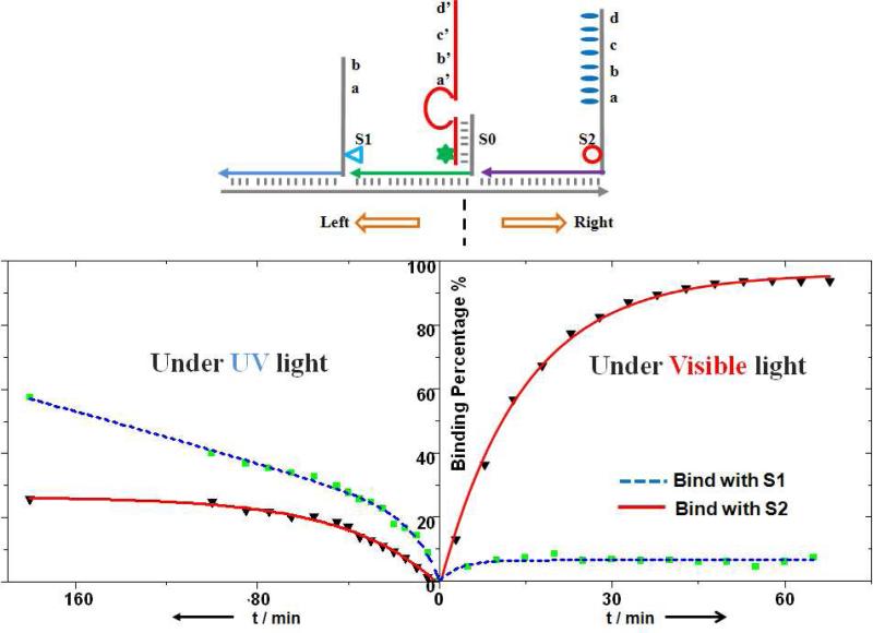
Figure 3.
Programmed control of route selection at a junction. Left turn (S0→S1) was achieved under UV light irradiation, and right turn (S0→S2) was induced by visible light. The fractions of the walker (labeled with Dabcyl, star) moving towards S2 (labeled with TAMRA, circle) or S1 (labeled with FAM, triangle) were monitored based on the fluorescence intensity change and further calculated using a standard calibration curve.

