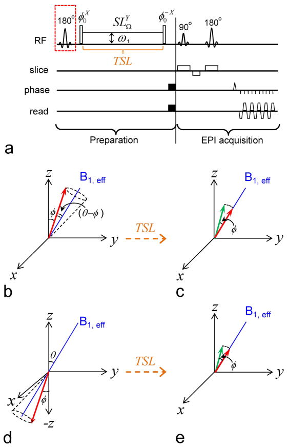
Fig. 1. Pulse sequence and magnetization trajectories.
(A) Pulse sequence for the Irradiation with Toggling Inversion Preparation (iTIP) approach. A spin-locking (SL) module is applied following a toggling inversion pulse, indicated by a red dashed square. The super- and subscripts of an RF pulse denotes its phase and transmitter frequency, respectively. Water magnetization differs at the initial condition with inversion pulse toggled “off” (B–C) and “on” (D–E). In either case, the water magnetization is flipped by a φ pulse and then “locked” by an SL pulse with frequency offset Ω, a Rabi frequency of ω1 and a spin-locking time (TSL). Consequently, the water magnetization (red arrow) precesses around B1,eff by an angle (θ - φ), relaxes with time constant R1ρ (B, D), and reaches the same steady state if TSL is sufficiently long. For finite TSL in the transient state, the magnetization is larger than the steady state in (C), whereas it is smaller than the steady state in (E). Following the SL pulse, the 2ndφ pulse flips the magnetization (red arrow) back toward the Z-axis for imaging (green arrow). The image readout is EPI in this example, but can be replaced by other fast acquisition methods.

