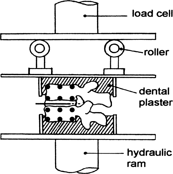
Fig. 1.
A two-vertebra specimen subjected to compressive loading by a hydraulic materials testing machine (anterior on left). The height of each roller could be adjusted to allow the specimen to be loaded in pure compression (as shown) or in flexion (height of the anterior roller increased). Black circles indicate the six reflective markers attached to each vertebral body. (A photograph of such a specimen was published previously [14].)

