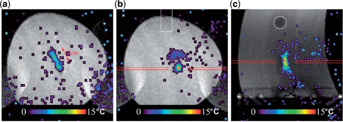
Figure 4.
Real-time MRI target tracking. Temperature maps obtained after 60 s of HIFU ablation on a phantom subjected to periodical motion. The imaging slice was placed either orthogonal to the symmetry axis of the HIFU transducer (a, b) or parallel to the symmetry axis (c). (a) The temperature distribution of non-compensated (i.e., HIFU beam steering disabled, but MR temperature mapping fully motion compensated) HIFU ablation shows the energy dispersion along the motion trajectory. In this example the motion vector of the phantom is parallel to the image plane and is indicated by the red arrow. (b) The fully motion-compensated HIFU ablation shows that the beam energy is deposited at the predefined location. (Reprinted from Ries et al.[39] with permission.)

