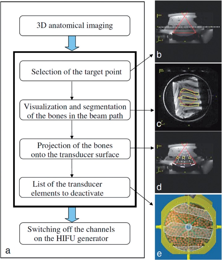
Figure 5.
Selective deactivation of individual transducer elements that have a rib in the beam path. (a) Schematic diagram of the proposed method for selecting the transducer elements to be deactivated. Anatomical images are used for (b) selection of the target point (the solid red lines show the HIFU propagation cone on a transverse slice and the white dashed line shows the horizontal slice displayed in c); (c) Manual segmentation of the bones (ROIs) within the beam path (circle). (d) Projection of the shadow of the ROIs onto the transducer surface (white bars on the transducer surface) by ray tracing from the targeted point (white dashed lines). (e) Visualization of the shadow of the ROIs on the 256 transducer elements distributed on the transducer surface, and determination of the elements to be deactivated. (Reprinted from Quesson et al.[44] with permission.)

