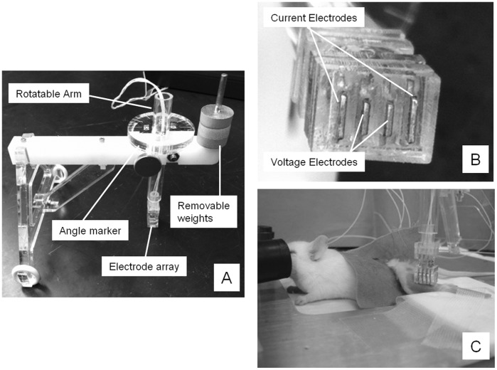
Figure 1. Multiple views of the device.
A. The entire device, showing the rotatable arm used to change the direction of the electrode array, the angle marker, and the removable weights; B. A close-up view of the tetrapolar electrode array; C. the entire animal setup with the device overlying the gastrocnemius muscle.

