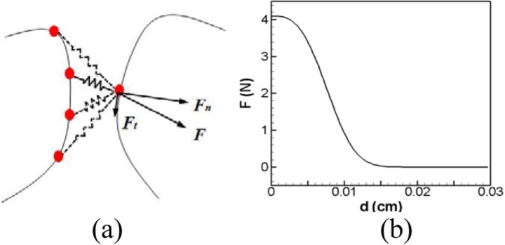
Figure 2.
(Color online) (a) Illustration of the nonlinear spring-based contact force. Each surface vertex of the triangular mesh on one VF is connected to every surface vertex on the opposite VF with non-linear springs. The solid line represents activated springs and the dashed line represents inactivated springs. “F” is the spring force and it is further decomposed into “Fn” and “Ft,” which are the normal and tangential components with respect to the local curvature of the VF surface, respectively. (b) Spring force versus distance between two contacting nodes.

