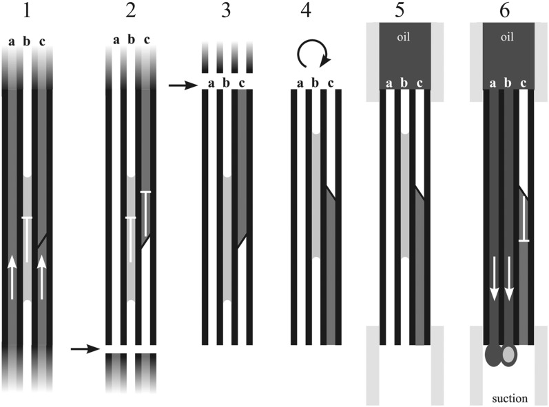
Figure 7.
Schematics present the technical steps involved in collecting sap from nonfunctional vessels. 1, An intact plant with functional vessels under tension (a and c) and a nonfunctional vessel partially filled with water (b). 2, Collection starts with the first cut made in the air. This would allow water under tension to be sucked toward the leaves in vessels a and c but not the water present in vessel b. In vessel c, water would only be sucked to the nearest border pit field. 3, Within several seconds following the first cut, a second cut is made and a portion of stem (3–4 cm) long is removed. It presumably contains some water under tension stuck on the bordered pit field (c) and water in nonfunctional vessels. 4, The section is then inverted and both ends are fitted to flexible tubes. 5, The upper tube is then filled with low-viscosity silicon oil and the lower end is fitted to a vacuum system. 6, A vacuum is generated that sucks oil through the empty vessels (a) and vessels that are open across the stem but filled with water droplets (b). However, the vacuum is not adequate to break water away from the border pit field (c). Oil containing small volumes of water from nonfunctional vessels is collected in centrifuge tubes and protects small droplets from evaporation in vacuum conditions. After several collection cycles, centrifuge tubes are spun and water is separated from oil at the bottom of the tube. Arrows and flat-ended lines represent the movement of water in vessels during the procedure of water collection.

