
Figure 2.
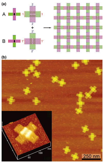
Origami Tiles with Orthogonal Directions of Propagation. (a) Schematics of the Tiles. Two different tiles, A and B, are shown. At left are simplified drawings showing the orthogonal nature of the tile propagation directions, their twofold axes, with color-coded sticky ends, red and blue. In a more realistic representation to the right the tiles are shown with their sticky end sets labeled with the numbers 1 and 2, as well as their complements 1′ and 2′; these images were generated by the program NanoEngineer (www.nanoengineer-1.net). The purple rectangular domain lies above the green rectangular domain in both tiles. This leads to the woven pattern shown on the right when the two tiles are combined. Note that there is a cavity in the green domain which is drawn horizontally in the A tile and vertically in the B tile. Except for the sticky ends, the two tiles are the same. (b) Atomic Force Micrographs of the A tile. Individual tiles are seen to form the cross-like structures shown in (a). The inset at the lower left emphasizes the overlap of the two domains that flanks the cavity. The cavity is visible and flanked clearly by the white region, which represents a thicker system (see Supporting Information).