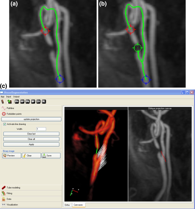
Fig. 2.
Failed pathline detection in a stenotic case (a) and even after an intermediate point (green marker) was added to help the pathline detection (b). Allowing user to draw a freehand curve on the projection image (the red curve in the right panel at figure c), a forbidden plane (white dots) does not allow the front propagation to pass through, resulting in the correct pathline inside the stenosis

