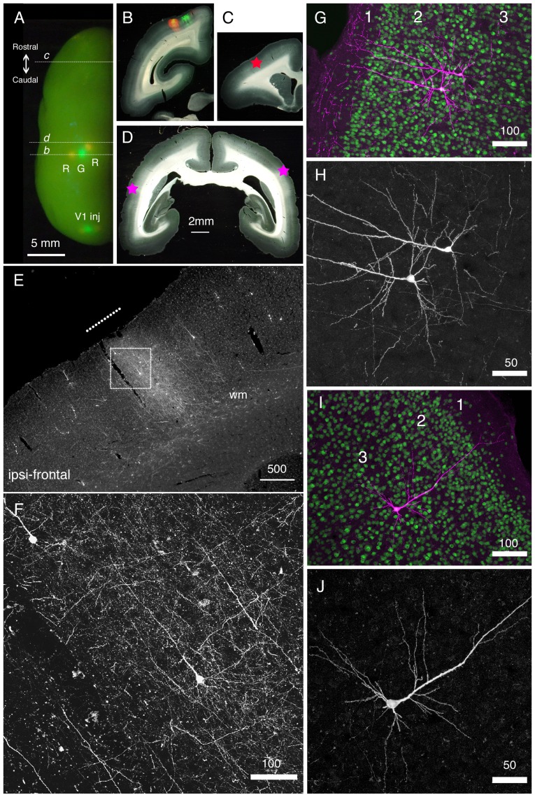
Figure 7. Long-distance cortical connection of the marmoset brain visualized by StTTrR/FuG-B vector.
(A) The left hemisphere of the marmoset brain with cortical vector injections is shown from above. StTTrR/FuG-B vector was injected into two sites in the parietal areas and two sites in V1 and StTTrG/FuG-B vector was injected into one site in the parietal area and one site in V1, as indicated. The injection sites were visualized by LED illumination. (B–D) The coronal sections at the positions indicated in panel A. The fluorescent image is overlaid on the dark field image of the section in panel B. The asterisk in panel C shows the position of the image shown in panel E. The asterisk in the left side of the section in panel D corresponds to the ipsilateral side. (E) The frontal cortex ipsilateral to the vector injection. At this plane, the forward projection fibers of RFP were visible (shown by a white line in panel E), together with retrogradely labeled cell bodies. (F) Confocal image of the boxed region in panel E. Dense axonal fibers and dendrites were visible. This is the fluorescence image of RFP with no antibody enhancement. (G–J) Confocal images of the corticocortical neurons. RFP signals are enhanced by immunofluorescence (magenta) and counterstained with NeuN antibody (green) in panels G and I. Only the RFP signals are shown in panels H and J. The two neurons in panels G and H and one neuron in panels I and J are ipsilateral and contralateral to the injection site, respectively. Bar: 5 mm for A; 2 mm for B–D; 500 µm for E; 100 µm for F, G and I. 50 µm for H and J.

