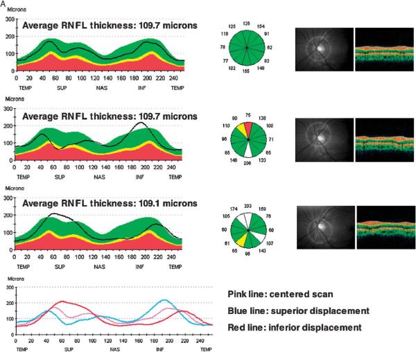
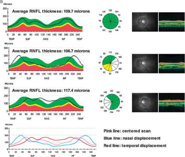
FIGURE 6.
A, Sample RNFL scan with displacement occurring along the vertical axis. The superimposed RNFL double hump profile patterns show apparent sectoral thinning in the displaced scans (bottom 2 scans) compared with the centered scan (top scan) whereas the opposite sectoral RNFL thickness is increased. The average RNFL thickness remains relatively unchanged. B, Sample RNFL scans with displacement occurring along the horizontal axis. The average RNFL thickness is increased in the temporally displaced scan (bottom scan), but did not increase in the nasally displaced scan (middle scan) compared with the centered scan (top scan).


