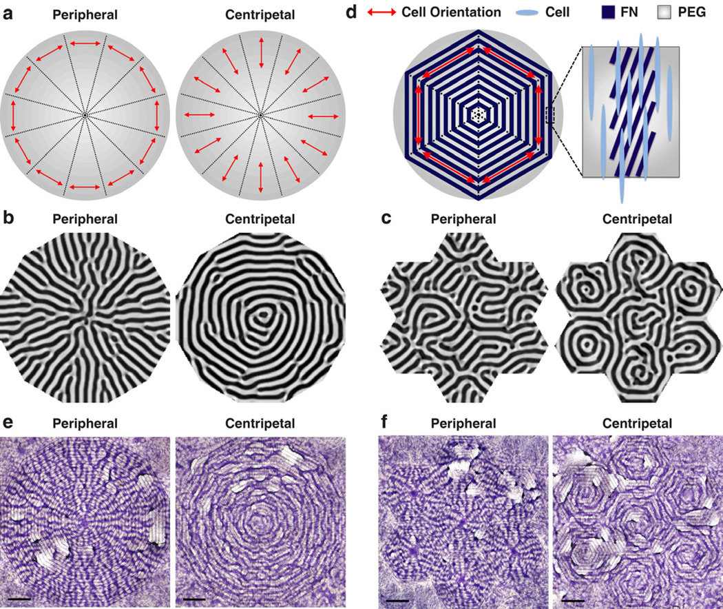
Fig. 3.
Directed pattern formation using model predictions and controlled cell orientation. (a) Schematics of θ distribution. (b) Computational simulations showing n(x, y) as a single pattern of radial structures or concentric rings. (c) Computational simulations showing n(x, y) as 6 repeated radial or ring patterns following hexagonal packing. (d) Schematics of desired θ* as peripheral orientation in 6 equal partitions. The FN stripes within each 300 µm-wide band were rotated to θ* − 20° to compensate for the VMCs’ left-right asymmetry which leads to 20° cell orient ation relative to the FN/PEG interface. In this example, to implement the desired θ* as 30°, 90°, and 150° relative to the horizontal a xis, the FN stripes in each band were designed as 10°, 70°, and 130°, respectively. Furthermore, each 300 µm-wide band was spaced in parallel with the 300 µm-wide PEG band to unify the θ* distribution within each partition. (e) VMC pattern formed as radial structure or concentric rings. Scale bar, 2 mm. (f) VMC pattern formed as 6 repeated radial or ring patterns following hexagonal packing. Scale bar, 2 mm. Multicellular ridges were stained purple with hematoxylin in (e) and (f).

