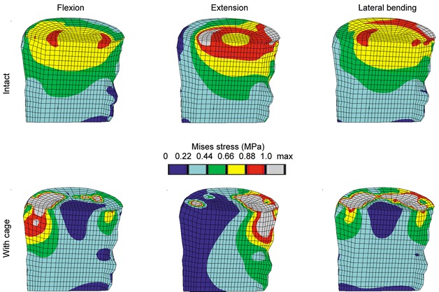
Fig. 5.

Von Mises stress distribution due to different loading conditions for the intact case (top row) and the models with cage (bottom row). The lateral bending occurs to the side shown. A sagittal cut through the cancellous bone of L3 is shown, anterior is to the left. The limits for the colour bands are based on the intact case. All models had an elastic modulus for cancellous bone of 100 MPa, and a titanium cage was used
