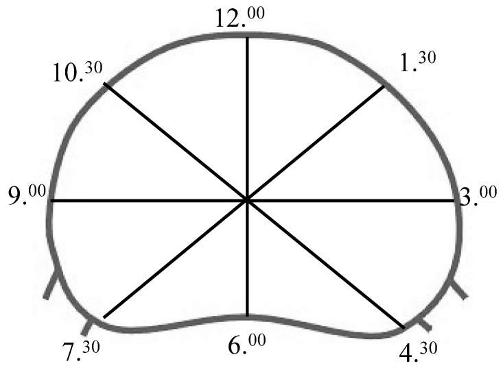
Fig. 2.
Schematic line drawing of a specimen including the superior endplate, view from above onto the superior endplate. Note the lines indicating how the specimens were scanned by computed tomography. The 6.00–12.00 line was defined to be the midsagittal line, the 9.00–3.00 line was defined to be perpendicular to the midsagittal line through the widest portion of the endplate, the 7.30–1.30 and 11.30–4.30 lines were defined to be in an 45° angle to the above mentioned lines

