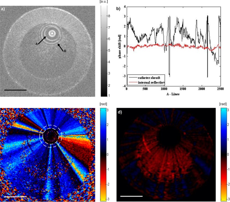
Fig. 3.
Imaging of a slow flow phantom. (a) Structural image of 1.5% blood in saline mixture within the tube, where arrow A indicates the internal reflection of the imaging optics, and arrow B indicates the outer surface of the imaging catheter sheath. (b) Phase shift obtained from the internal reflection indicated by arrow A and catheter sheath indicated by arrow B in (a). The phase shift of the catheter sheath is the median of data along the catheter thickness. (c) Doppler shift image of the slow flow phantom. The dashed ring indicates the sheath of the imaging catheter, with phase shift induced by NURD in a radially constant manner throughout the image. (d) Doppler image after suppression of the motion artifact, which displays the phase shift induced by the slow flow inside the tube phantom. Scale bars = 1 mm.

