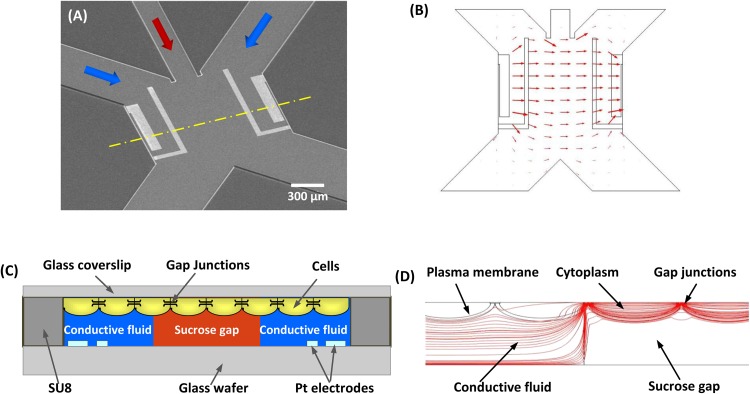
Figure 1.
(a) SEM of the sucrose-gap chip. Three inlet channels are connected to a sensing channel that is defined by two pair of electrodes on either side. Downstream two outlet channels split the solution into separate reservoirs. (b) Numerical simulation of current distribution, showing that the electrical field is confined in the sensing chamber (comsol/multiphysics). (c) A cross-section view of the sensing channel along the dashed line in (a), showing how a non-conductive sucrose gap is created by the middle stream so the electrical pathway is only through the confluent cells. (d) Cross-section view of current distribution in the flow chamber containing confluent cells. The conductivity of cytoplasm, cell membrane, and gap junction was 0.1, 0.2 × 10⁻⁶, and 1 × 10⁻⁴ S/m, respectively. The parameters are from Refs. 38, 39. It shows that the current lines are concentrated through the cell sheet in the gap region.

