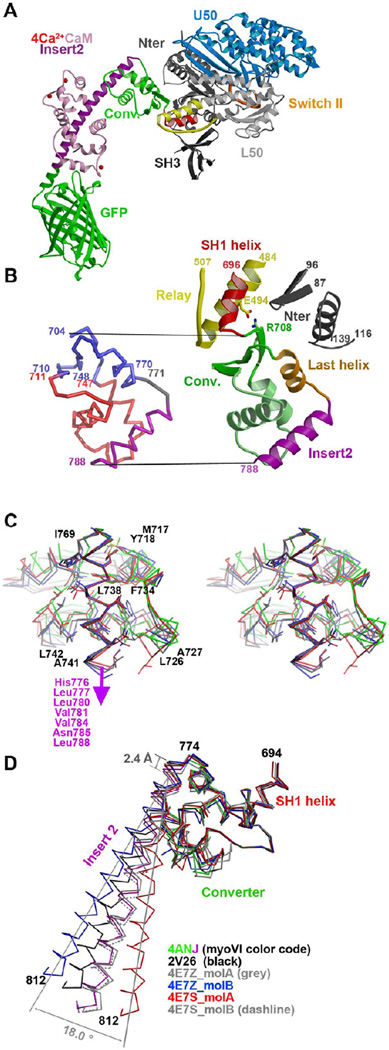
Figure 2. Variability in the converter of myosin VI in different pre-powerstroke state structures.
(A) The structure of the myosin VI MDins2-GFP prior to force generation (pre-powerstroke state) is shown with the motor sub-domains and important structural motifs indicated in colors (Switch II in orange, relay in yellow and SH1 helix in red). Insert-2 and calmodulin are shown in purple and pink, while the GFP fusion is in green. (B) (Left) The converter and its contacts with the Relay and the N-terminus subdomain are shown with the same color code as in A (except for the last helix shown in orange). (Right) A ribbon structure of the converter is displayed with the conserved regions indicated in blue and the variable regions in red. The hinge and the insert-2 are indicated in grey and purple, respectively. (C) Cross-eyed stereo view of the variable interactions between insert-2 and the rest of the converter in different PPS structures superimposed on insert-2 (4ANJ in green (converter) and purple (insert-2), 2V26 in black, 4E7Z_molB in blue and 4E7Z_molA in red). (D) The converter in the pre-powerstroke state of myosin VI. A superposition on the converter of the six different PPS structures is shown with the same color code as in C. Note that overall the variation in the P-fold conformation of the converters result in different orientations of the insert-2 proximal helix. Modeling of the full insert-2 helix is shown to highlight the degree of variability in the insert-2 orientation.

