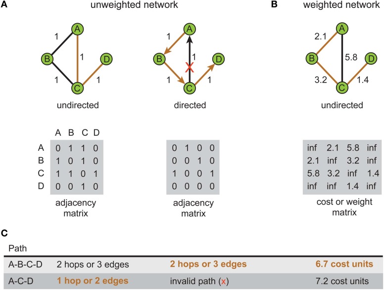
Figure 1.
Shortest path for the same problem can be different depending on the type of network representation used. An example network consists of four labeled vertices A, B, C, and D. The aim is to find shortest path between vertex A to vertex D. (A) Unweighted network representation. The topology of undirected (left) and directed versions (right) is shown graphically (top) with their corresponding adjacency (connectivity) matrices below (bottom). Brown lines show shortest paths. Red cross indicates a counter-directional edge, which creates an invalid path from vertex A to vertex D. (B) Weighted network representation. Graphical representation (top) of an undirected weighted graph with values of weights (distance) shown next to edges and recorded in the cost or weight matrix below (bottom). Note in the cost or weight matrix the absence of an edge is recorded as an infinite cost (“inf”) while in adjacency matrix it is recorded as zero. (C) Summary table for path length results corresponding to each type of network. Shortest paths are shown in bold brown text.

