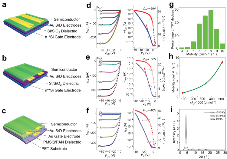
Figure 2. Illustrative OTFTs with channel semiconductor 1 and their FET characteristics in ambient conditions: (a) and (b) are respectively schematic BGTC and BGBC devices on Si wafer while (c) is a schematic BGBC device on flexible PET substrate.
For devices (a) and (b), the Si/SiO2 surfaces were first modified with alkyl silyl self-assembled monolayers (SAMs) from octyltricholorosilane and octadecyltrichlorosilane respectively before semiconductor was deposited by spin coating. The heavily n-doped Si wafer substrate served as a common gate electrode for these devices while vacuum deposited gold (Au) features served as the source/drain electrodes. For device (c), vacuum deposited Au gate and source/drain electrodes were separated by a spin-cast PMSQ/PAN dielectric layer modified with octadecylsilyl SAM, and the semiconductor was deposited by spin coating directly on source/drain electrodes on the dielectric surface. (d), (e), and (f) are the respective output curves and transfer characteristics of devices(a), (b)and (c). The mobility distribution for over 200 devices of (a) and (b) is summarized in (g), showing mobility ranging from 3 cm2 V−1 s−1 to about 10 cm2 V−1 s−1. The dependence of average saturated mobility of five representative devices on semiconductor weight-average molecular weight (Mw) is depicted in (h). Increased crystallinity of a thin film (~100 nm) of semiconductor 1 as a function of increasing Mw is reflected by increased intensity of XRD diffractions as shown in (i).

