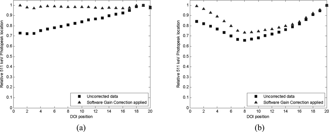
Fig. 4.
Distribution of normalized photopeak positions along the crystal depth. Left: 2×2×20 mm3 crystal with a 30 µm finish. An obvious mismatch is apparent between the gains at either end. Right: 1.5×1.5×20 mm3 crystal with a saw cut surface finish. In this crystal there is both a gain mismatch and severe light loss at the central depth region. A software level gain correction has been applied (triangles) to mitigate the effect of gain mismatch.

