
Figure 12.
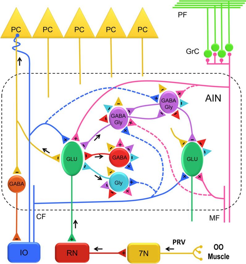
Organization of the AIN circuit. A schematic representation of different neuronal populations and their connections in the AIN. The premotor pathway of the OOM is shown with black arrows that delineate the direction of PRV labeling. Two representative glutamatergic (GLU) projection neurons are shown. A PRV-labeled third-order GLU neuron projecting to the red nucleus (RN) is depicted with a black arrow. Three types of PRV-labeled fourth-order interneurons are shown to make a direct connection onto the PRV-labeled GLU neuron. Possible connections among different AIN neurons are represented with excitatory (+) and inhibitory (−) terminals (colored triangles). Excitatory input reaches the AIN by mossy fiber (MF) and climbing fiber (CF) collaterals that make connections on GLU neurons and possibly (dashed lines) on different interneurons. Inhibitory input to AIN neurons is provided by Purkinje cells (PC) and local interneurons. 7N, Facial nucleus; GrC, granule cell layer; IO, inferior olive; PF, parallel fibers.