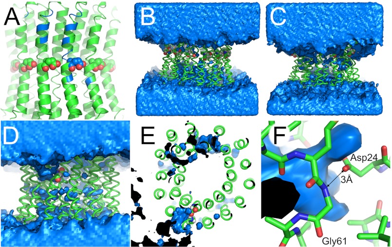
FIGURE 2.
The water channel in different simulations. The lipid bilayer is omitted for clarity. A, map of the water channel from Fig. 1 on the starting structure. Blue, main amino acids in contact with the water channel (see Table 2 for a list). B and C, comparison of water distribution in control MD simulations. B, c-ring with Glu61 of all 14 protomers protonated (uncharged). C, c-ring with all Glu61 deprotonated. Although the protonated ring (B) does not show a distinct water channel, a water ring is drawn toward the charged center of the c-ring (C). D–F, water channel in suppressor mutant cP24D/E61G. D, front view. The water channel developed from the top (n-side) to the one charged Asp24. This channel is inclined to the vertical membrane normal and runs, as depicted here, from the top left to the center. E, top view. The water channel reaches as far as the carboxylate group of Asp24. F, close-up view. The carboxylate group of Asp24 establishes a hydrogen bond with the amide nitrogen of Gly61 with a distance of 3 Å. Gln28 is hidden for clarity. A–D and F, top, n-side; bottom, p-side. A–C, spheres show Glu61 of c-protomers. D–F, spheres show cAsp24. B–F, blue, water density at a contour level of 50 waters/Å3 over the course of the simulation. Black, inside of water density.

