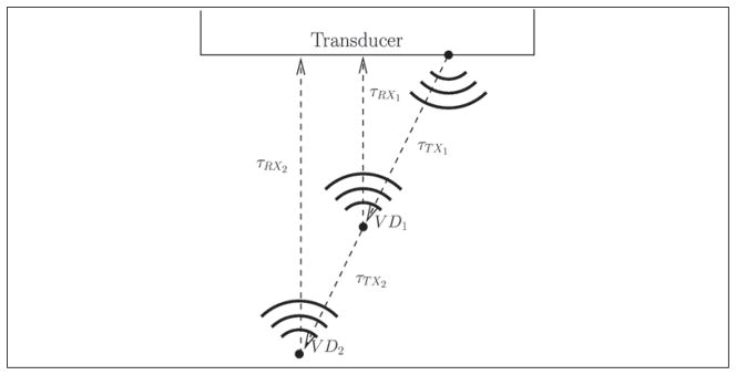
Figure 2.
This figure demonstrates a potential geometry of two virtual detectors (each denoted by VD) and the transducer. The time delays are indicated by τTXi for the time from the transducer surface to the virtual detector and τTXi for the time from the virtual detector to the transducer’s surface.

