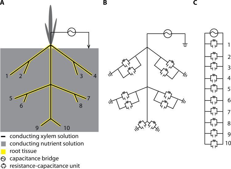
Fig. 1.
Resistance-capacitance (RC) circuits according to the Dalton (1995) model. (Panel A) Diagram of a plant root system with 10 root tips showing the tissue separating the xylem solution from the nutrient solution. (Panel B) Electrical equivalent network of the root system showing the location of the RC components. (Panel C) Equivalent circuit for the root system. Note that the individual RC components can have different values.

