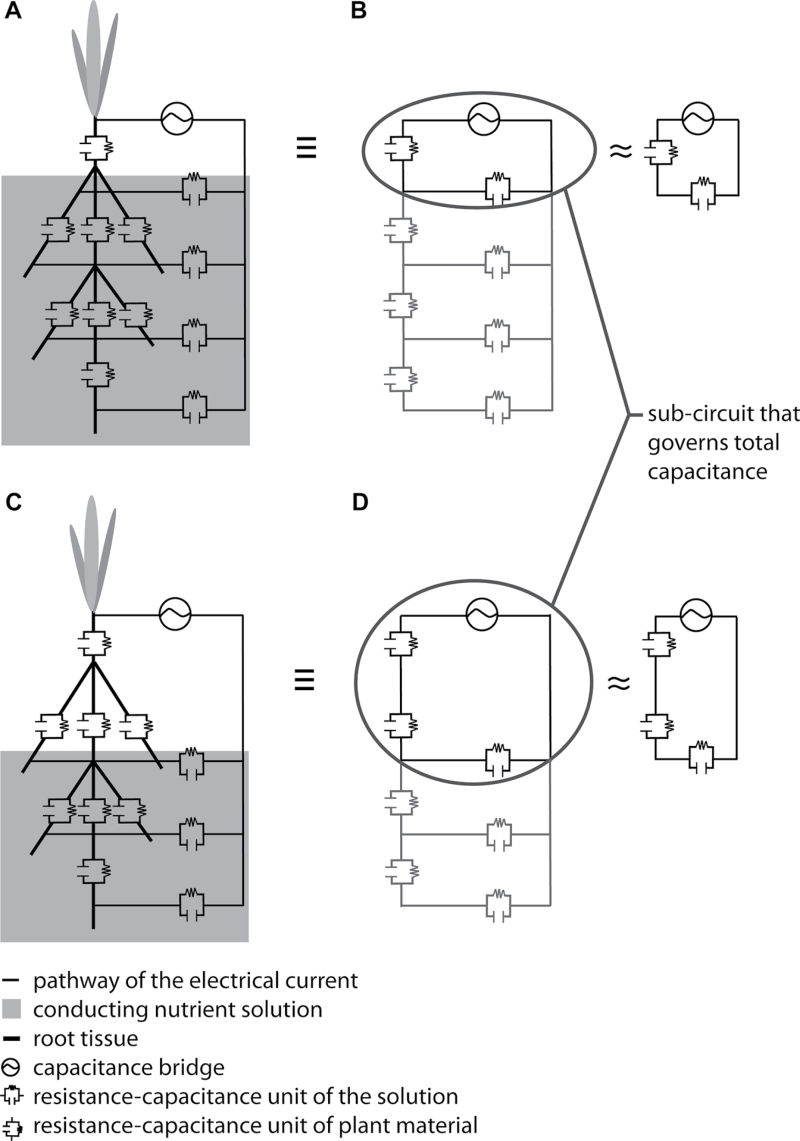
Fig. 10.
Resistance-capacitance (RC) circuits according to the revised model. (A, C) Diagrams of barley plants with five root tips; (B, D) Electrical equivalent networks of the root systems showing the location of the RC components. (A, B) RC circuits for a completely submerged root system; (C, D) RC circuits for a partly submerged root system. The subcircuit that largely determines the capacitance is ringed to emphasize its importance. Note that the individual RC components can have different values.

