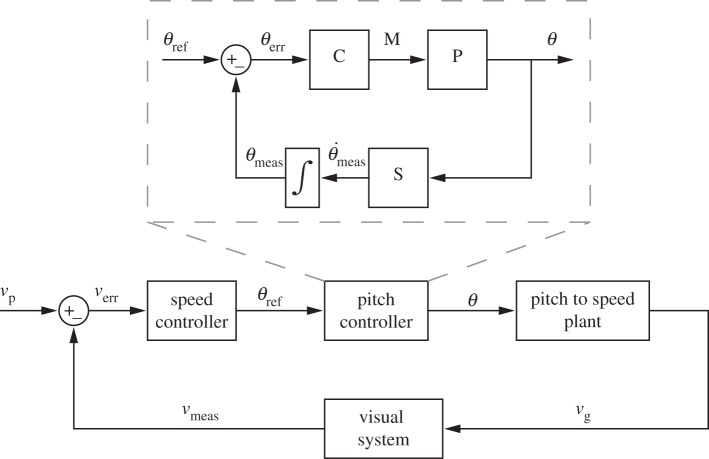
Figure 1.
Hierarchical flight speed control scheme. An outer visual loop sets the desired pitch angle (θref) according to the error between the preferred speed vp and the measured ground speed vg. In the inner pitch control loop (inset), the pitch controller C sets the pitch angle θ to the desired value θref by producing a torque M around the pitch axis. P represents the plant for pitch rotation. The sensor S, representing the halteres and the visual system, measures the rotational speed  which is then integrated to get the measured pitch angle θmeas. The pitch angle θ is converted to vg via the pitch-to-speed plant.

