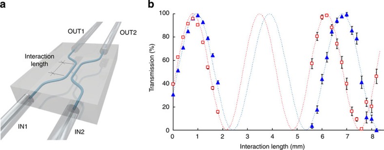
Figure 1. Partially polarizing directional couplers.
(a) Schematic representation of a waveguide directional coupler; IN1 and IN2 are the input ports, whereas OUT1 and OUT2 are the output ports of the device. (b) H (squares) and V (triangles) polarization transmissions of directional couplers with different interaction lengths, based on slightly birefringent waveguides. First, the 0–2 mm interaction length range was investigated to evaluate the beating length difference between the two polarizations; the interval of interest to obtain the required PPDCs was estimated to be in the 5.6–8.2 mm range, which was consequently explored. Transmission for 0 mm interaction length is non-zero, because some coupling already occurs in the curved portions of the approaching/departing waveguides. Error bars indicate fabrication reproducibility.

