Figure 9.
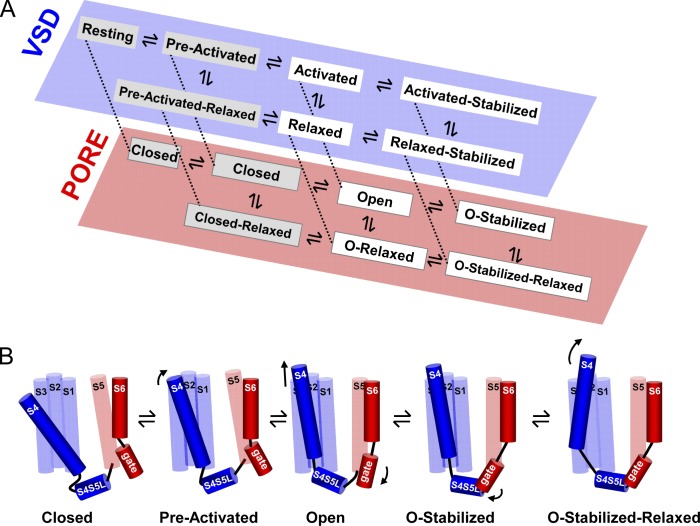
State model and cartoon of the activation path in Shaker and Kv1.2. (A) Proposed simplified state diagram for Shaker and Kv1.2 channels whereby the state occupancy for both VSD (blue) and BC (red) gates are represented in two separate schemes. The stabilization imposed by the BC gate is termed the open stabilized (O-stabilized) state and results in the activated stabilized state at the VSD level. The stabilization that originates from the VSD relaxation process results in the relaxed and open relaxed (O-relaxed) state of the VSD and BC gate, respectively. (B) Cartoon of the structural path followed by Shaker and Kv1.2 channels upon a membrane depolarization. For clarity, only one out of four subunits is illustrated, and the specific change from one state to the next is indicated by an arrow. During a depolarization, the VSD (mostly the S4 segment) moves from its resting position (at the extreme left) to its preactivated state and in a subsequent concerted step to its activated state, resulting in the opening of the BC gate (open). Because in Shaker and Kv1.2 the stabilization imposed by the BC gate (depicted by the interaction between the S4S5L and S6 gate region) develops first, the BC gate evolves from the open to the open stabilized (O-stabilized) conformation. When the depolarization is prolonged, the VSD relaxes (illustrated with a tilt of the S4), and the channel populates its final open stabilized relaxed (O-stabilized-relaxed) state.

