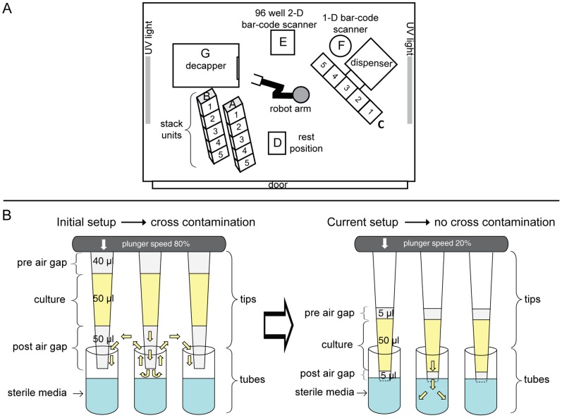
Figure 3. Automated sub-cultivation with LHS1.
(A) Schematic layout of the equipment within the LHS1 cabinet. Positions A and B represent stack units where racks of 2D tubes and deep well plates are stored prior to operations. Position C designates the 5-position, XY-moveable stage for the 96-tip pipettor. Position D represents a rest position used for regripping of racks of 2D tubes before and after capping/decapping in position G. Positions E and F represent 2-D and 1-D bar-code readers. H is a SCARA robotic arm for moving between these positions. Further details of how LHS1 was used are presented in File S2, Figs. S6/S8 for sterile dispensing of media into 2D tubes, and S7/S9 for aseptic sub-cultivation of bacteria into 2D tubes and deep well plates. (B) Improvements in pipetting parameters (right) which eliminated aerosol formation that led to cross-contamination between cultures (left).

