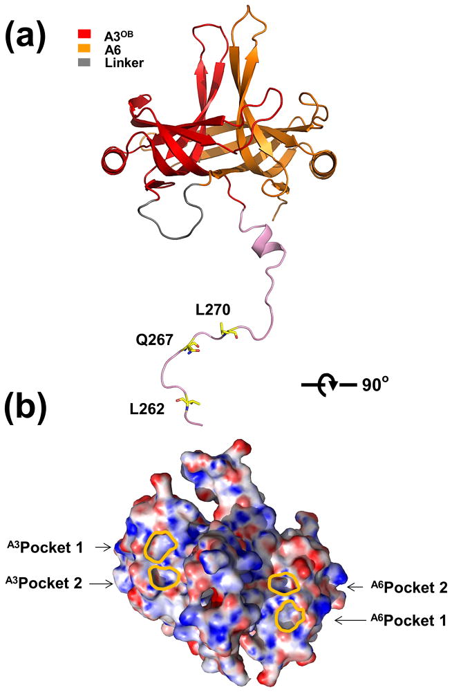
Fig. 2. Overall structure of T. brucei A3OB-9aa-A6.
(a) Overall structure of A3OB-9aa-A6. The structure of the A3OB-aa9-A6 is shown as a ribbon diagram with the A3OB domain, A6OB domain, linker 9aa and N-terminally extended sequences of A3OB depicted in red, yellow, grey and pink, respectively. Three residues of the long N-terminal extension of A3OB interact with Pockets 1 and 2 shown in (b).
(b) Electrostatic surface representation of the A3OB-9aa-A6 structure. The A3OB-9aa-A6 structure is rotated ~ 90° with respect to panel (a). The electrostatic potential surface of A3OB-9aa-A6 was calculated using APBS (Baker et al., 2001). Regions with potentials above +25 kbTec−1 and below −25 kbTec−1 are shown in blue and red, respectively. The locations of A3OB and A6OB pockets are indicated with lines in gold, respectively.

