
Fig. 2.
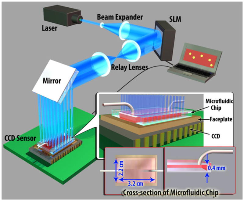
The schematic diagram of the high-throughput fluorescent imaging set-up (not to scale). A structured illumination array is used to excite and laterally scan the fluorescent specimens located within a large-area microfluidic chip (~ 22 × 32 × 0.4 mm). The PC, SLM and the CCD are synchronized using a custom developed LabView interface, rapidly acquiring an entire sequence of 144 lensfree images in ~36 seconds.